ADDITIVE MANUFACTURING TECHNOLOGIES
(An Overview)
Introduction.
Manufacturing technology can be classified as either Conventional or Non-Conventional processes. The Conventional processes have been in existence since prior to 1950, and the non-conventional processes are those that have been both adopted and implemented since the 1950s.
Nowadays technology enthusiasts are frequently using a term called Additive Manufacturing/ 3D-Printing. This technology is becoming very much popular in present time and can be considered as a paradigm for Traditional (Subtractive) Manufacturing area. Everybody recognizes this term nowadays but what many people mean when talking about 3D printing is actually one of the several Additive Manufacturing (AM) processes.
In 2009, ASTM Committee F42 was formed to develop standards for additive manufacturing. An important contribution of Committee F42 has been the development of a terminology standard that defines the different processes required to build 3D parts from computer-aided design (CAD) files. Additive manufacturing, or AM processes, initially known as Solid Freeform Fabrication (SFF) and Rapid Prototyping (RP) and currently described as Direct Digital Manufacturing (DDM), or Rapid Manufacturing (RM), Art to Part (AtP), Additive Layer Manufacturing (ALM), or Layer Manufacturing (LM), were originally developed in the late 1980s to early 1990s.
Definition (Layer by Layer Principle).
As per the ASTM standards "Additive Manufacturing (AM)" can be classified as a (ASTM International, 2012): "process of joining materials to make objects from 3D model data, usually layer upon layer, as opposed to subtractive manufacturing methodologies, such as traditional machining.”
Additive manufacturing (AM) can also be described in simple words as "process of joining or adding materials with the primary objective of making objects from three-dimensional (3D) model data using the layer-by-layer principle."
Additive manufacturing (AM) can also be described in simple words as "process of joining or adding materials with the primary objective of making objects from three-dimensional (3D) model data using the layer-by-layer principle."
Additive Manufacturing (Layer by Layer Principle)
Process Chain for AM.
Conceptually, AM is an approach where 3D designs can be built directly from a Computerized-Aided Design (CAD) file without any part-specific tools and dies.
Additive Manufacturing includes certain steps which one has to follow so that he/she can begin the production process. These steps are compiled together and termed as a Process Chain for AM. These steps can be better understood by the following figure.
Additive Manufacturing Process Chain showing important stages of production.
So how exactly does Additive Manufacturing work?
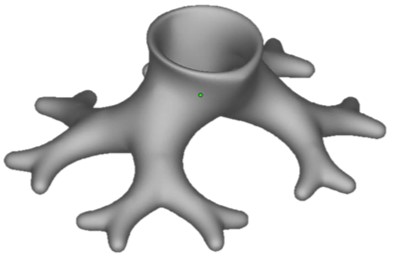
The first step is to create a 3D model of the object to be printed. This model can be designed with computer-aided design (CAD) software or through reverse engineering techniques by for example using an object laser scanner.
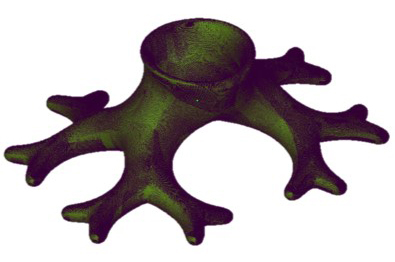
The CAD file is then converted to a standard additive manufacturing file format - usually an STL file. This step is regarded as the simplest. Conversion to a STL file will tessellate shapes and the time needed to do this depends on PC power and model complexity. The file is then digitally sliced into layers.
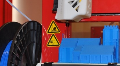
The third stage requires the transfer of the STL file and setting up of the machine. In order to print economically i.e. maximise cost savings and reduce material waste, the positioning and sizing of the object on the build platform should be checked – usually multiple parts are printed in one go.
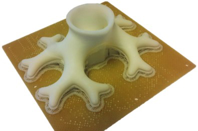
In the fourth step, the machine which is only controlled by a computer builds the model layer by layer. The layer thickness dictates the final quality and depends on the machine and process. For Fused Deposition Modelling a layer thickness of 0.254 mm is typical, for Stereolithography printing can result in a quality of 0.05 – 0.1 mm. The size of a model depends on the machine size.
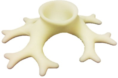
After building the part and potentially applying cooling and curing periods, the model can be removed from the machine. Additional post-processing can occur such as cleaning, polishing, painting and finishing of the surface to the desired standard. This may involve the use of other machines and tools.
Subtractive vs Additive Manufacturing.
Subtractive Manufacturing can be defined as a process of producing parts by subtracting the unnecessary material from the block of goods. Metal Cutting, Metal Forming, Metal Casting, Non-Traditional Machining, Molding etc. all are included in subtractive manufacturing.
On the other hand, Additive Manufacturing allows a user to fabricate component directly using printers by following layer by layer principle. Direct Metal Laser Sintering (DMLS), Selective Laser Sintering (SLS), Selective Laser Melting (SLM), Fused Deposition Molding (FDM) etc. all are available AM technologies.
Advantages and Challenges in AM.
As everyone knows that AM can provide us the freedom to design anything which cannot be done using traditional way of manufacturing. But instead of having several advantages associated with the AM over traditional still several challenges are available which have to be overcome to make it a more suitable process for manufacturing point of view.
Categorization of AM Technologies.
According to ASTM F2792, AM Technologies can be categorized into seven different categories which can be better understood by following flowchart:
Let us understand these AM technologies one by one in detail.
Binder Jetting.
In the late 1980s, Sachs et al. invented the 3DP technology (commercial name for Binder Jetting) that was later patented to print plastic, ceramic, and metallic parts.
Binder Jetting is defined as "an additive manufacturing process in which a liquid bonding agent is selectively deposited to join powder materials". In this binding mechanism can be thermal and/or chemical one.
Commercial Tech: 3-Dimensional Printing (3DP).
Schematic of Binder Jetting Process.
Binder Jetting Process: https://www.youtube.com/watch?v=ONMYx1yhJuo
Materials.
Metals: Stainless steel.
Polymers: ABS, PA, PC.
Ceramics: Glass.
All three types of materials can be used with the binder jetting process.
Advantages and Disadvantages.
Advantages:
a) Parts can be made with a range of different colours.
b) Uses a range of materials: metal, polymers and ceramics.
c) The process is generally faster than other.
d) The two material method allows for a large number of different binder-powder
combinations and various mechanical properties.
Disadvantages:
a) Not always suitable for structural parts, due to the use of binder material.
b) Additional post-processing can add significant time to the overall process.
Directed Energy Deposition (DED).
In 1995, Sandia National Laboratories (SNL) developed DED with laser heat source. This technology was originally patented as Laser Engineered Net Shaping (LENS), a subset of DED.
Directed Energy Deposition is defined as “an additive manufacturing process in which focused thermal energy is used to fuse materials by melting as they are being deposited”. In this binding mechanism will be thermal.
Commercial Tech: Direct Metal Deposition (DMD), Laser Engineering Net Shaping (LENS).
Schematic of Direct Energy Deposition Process.
Direct Energy Deposition Process: https://www.youtube.com/watch?v=yKnlmfuMSgo
Materials.
Advantages and Disadvantages.
Advantages:
a) Ability to control the grain structure to a high degree, which lends the process to repair
work of high quality, functional parts.
b) A balance is needed between surface quality and speed, although with repair
applications, speed can often be sacrificed for a high accuracy and a pre-determined
microstructure.
Disadvantages:
a) Finishes can vary depending on paper or plastic material but may require post processing
to achieve the desired effect.
b) Limited material use.
c) Fusion processes require more research to further advance the process into a more
mainstream positioning.
Material Extrusion.
The technology was developed by S. Scott Crump in the late 1980s and was commercialized in 1990. It is a Material Extrusion process as per ASTM F2792.
Material Extrusion is defined as “an additive manufacturing process in which material is selectively dispensed through a nozzle or orifice”. In this binding mechanism will be thermal.
Commercial Tech: Fused Deposition Modelling (FDM).
Schematic of Material Extrusion Process.
Material Extrusion Process: https://www.youtube.com/watch?v=VQR_Q8_KhCs
Materials.
The Material Extrusion process uses polymers and plastics.
Polymers: ABS, Nylon, PC, PC, AB.
Advantages and Disadvantages.
Advantages:
a) Widespread and inexpensive process.
b) ABS plastic can be used, which has good structural properties and is easily accessible.
- Disadvantages:
- a) The nozzle radius limits and reduces the final quality.
- b) Accuracy and speed are low when compared to other processes and accuracy of the final model is limited to material nozzle thickness.
- c) Constant pressure of material is required in order to increase quality of finish.
Material Jetting.
Objet Geometries Ltd. was founded in 1998 and is based in Rehovot, Israel. They patented PolyJet Printing (commercial name for Material Jetting) and merged with Stratasys in 2012.
Material Jetting is defined as “an additive manufacturing process in which droplets of build material are selectively deposited”. Models produced by this process do not require post-curing.
Commercial Tech: Polyjet Modelling (PJM), Ballistic Particle Manufacture (BPM), Multi Jet Modelling (MJM).
Schematic of Material Jetting Process.
Material Jetting Process: https://www.youtube.com/watch?v=kbiIdTVz6bA
Materials.
The material jetting process uses polymers and plastics.
Polymers: Polypropylene, HDPE, PS, PMMA, PC, ABS, HIPS, EDP.
Advantages and Disadvantages.
Advantages:
- a) The process benefits from a high accuracy of deposition of droplets and therefore low waste.
- b) The process allows for multiple material parts and colours under one process.
- Disadvantages:
- a) Support material is often required.
- b) A high accuracy can be achieved but materials are limited and only polymers and waxes can be used.
- Powder Bed Fusion (PBF).
-
Deckard and Beaman started working on Selective Laser Sintering (SLS) (commercial name for PBF) technology in 1984 and made the first SLS machine in 1986. DTM Corp. commercialize this technology which later acquired by 3D Systems in 2001.
-
Powder Bed Fusion is defined as “an additive manufacturing process in which thermal energy selectively fuses regions of a powder bed”. In this binding mechanism will be thermal.
-
- Commercial Tech: Selective Laser Sintering (SLS), Direct Metal Laser Sintering (DMLS), Selective Laser Melting (SLM), Electron Beam Melting (EBM).

- Schematic of Powder Bed Fusion Process.
- Powder Bed Fusion Process: https://www.youtube.com/watch?v=te9OaSZ0kf8
Deckard and Beaman started working on Selective Laser Sintering (SLS) (commercial name for PBF) technology in 1984 and made the first SLS machine in 1986. DTM Corp. commercialize this technology which later acquired by 3D Systems in 2001.
Powder Bed Fusion is defined as “an additive manufacturing process in which thermal energy selectively fuses regions of a powder bed”. In this binding mechanism will be thermal.

Materials.
-
The Powder bed fusion process uses any powder based materials, but common metals and polymers used are:
SHS: Nylon.
- DMLS, SLM: Stainless Steel, Titainium, Aluminium, Cobalt Chrome, Steel.
- EBM: Titanum, Cobalt Chrome, SS, Al and copper.
-
The Powder bed fusion process uses any powder based materials, but common metals and polymers used are:
SHS: Nylon.
Advantages and Disadvantages.
-
Advantages:
- a) Relatively inexpensive.
- b) Suitable for visual models and prototypes.
- c) Ability to integrate technology into small scale, office sized machine.
- d) Powder acts as an integrated support structure.
- e) Large range of material options
- Disadvantages:
- a) Relatively slow speed (Selective Heat Sintering (SHS)).
- b) Lack of structural properties in materials.
- c) Size limitations.
- d) High power usage.
- e) Finish is dependent on powder grain size.
- Sheet Lamination.
-
Laminated Object Manufacturing (LOM) (commercial name for Sheet Lamination) was first introduced in 1991 by Helisys, USA.
- Sheet Lamination is defined as “an additive manufacturing process in which sheets of material are bonded to form an object”. In this binding mechanism can be thermal or thermochemical.
- Commercial Tech: Laminated Object Manufacturing (LOM), Paper Lamination Technology (PLT), Solid Foil Polymerisation (SFP), Ultrasonic Additive Manufacturing (UAM).

- Schematic of Sheet Lamination Process.
- Sheet Lamination Process:
- https://www.youtube.com/watch v=GUvnz0borAI
- Materials.
-
Effectively any sheet material capable of being rolled. Paper, plastic and some sheet metals.
The most commonly used material is A4 paper.
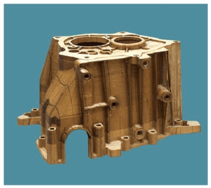
Advantages and Disadvantages.
-
Advantages:
- a) Benefits include speed, low cost, ease of material handling, but the strength and integrity of models is reliant on the adhesive used.
- b) Cutting can be very fast due to the cutting route only being that of the shape outline, not the entire cross-sectional area.
- Disadvantages:
- a) Finishes can vary depending on paper or plastic material but may require post processing to achieve desired effect.
- b) Limited material use.
- c) Fusion processes require more research to further advance the process into a more mainstream positioning.
- Vat Photo-polymerization.
-
In August 1984, Charles Hull, co‐founder and chief technical officer of 3D Systems, applied for a U.S. patent titled Apparatus for Production of Three‐Dimensional Objects by StereoLithography (SL) (commercial name for vat photo-polymerization), which was granted in March 1986.
-
Vat Photo-polymerization is defined as “an additive manufacturing process in which liquid photopolymer in a vat is selectively cured by light-activated polymerization”. In this binding mechanism will be chemical.
-
Commercial Tech: Stereolithography (SL), Solid Ground Curing (SGC).

- Schematic of Vat Photo-polymerization Process.
-
- Vat Photo-polymerization Process:
- https://www.youtube.com/watch?v=FtmgKYyeXnA
- Materials.
-
The Vat polymerisation process uses Plastics and Polymers.
Polymers: UV-curable Photopolymer resin.
Resins: Visijet range (3D systems).

Advantages:
- a) Relatively inexpensive.
- b) Suitable for visual models and prototypes.
- c) Ability to integrate technology into small scale, office sized machine.
- d) Powder acts as an integrated support structure.
- e) Large range of material options
- Disadvantages:
- a) Relatively slow speed (Selective Heat Sintering (SHS)).
- b) Lack of structural properties in materials.
- c) Size limitations.
- d) High power usage.
- e) Finish is dependent on powder grain size.
- Sheet Lamination.
-
Laminated Object Manufacturing (LOM) (commercial name for Sheet Lamination) was first introduced in 1991 by Helisys, USA.
- Sheet Lamination is defined as “an additive manufacturing process in which sheets of material are bonded to form an object”. In this binding mechanism can be thermal or thermochemical.
- Commercial Tech: Laminated Object Manufacturing (LOM), Paper Lamination Technology (PLT), Solid Foil Polymerisation (SFP), Ultrasonic Additive Manufacturing (UAM).

- Schematic of Sheet Lamination Process.
- Sheet Lamination Process:
- https://www.youtube.com/watch v=GUvnz0borAI
Laminated Object Manufacturing (LOM) (commercial name for Sheet Lamination) was first introduced in 1991 by Helisys, USA.

- Materials.
-
Effectively any sheet material capable of being rolled. Paper, plastic and some sheet metals.
The most commonly used material is A4 paper.

Advantages and Disadvantages.
Effectively any sheet material capable of being rolled. Paper, plastic and some sheet metals.
The most commonly used material is A4 paper.

Advantages:
- a) Benefits include speed, low cost, ease of material handling, but the strength and integrity of models is reliant on the adhesive used.
- b) Cutting can be very fast due to the cutting route only being that of the shape outline, not the entire cross-sectional area.
- Disadvantages:
- a) Finishes can vary depending on paper or plastic material but may require post processing to achieve desired effect.
- b) Limited material use.
- c) Fusion processes require more research to further advance the process into a more mainstream positioning.
- Vat Photo-polymerization.
- In August 1984, Charles Hull, co‐founder and chief technical officer of 3D Systems, applied for a U.S. patent titled Apparatus for Production of Three‐Dimensional Objects by StereoLithography (SL) (commercial name for vat photo-polymerization), which was granted in March 1986.
- Vat Photo-polymerization is defined as “an additive manufacturing process in which liquid photopolymer in a vat is selectively cured by light-activated polymerization”. In this binding mechanism will be chemical.
Commercial Tech: Stereolithography (SL), Solid Ground Curing (SGC).
- Schematic of Vat Photo-polymerization Process.
- Vat Photo-polymerization Process:
- https://www.youtube.com/watch?v=FtmgKYyeXnA
- Materials.
- The Vat polymerisation process uses Plastics and Polymers.Polymers: UV-curable Photopolymer resin.Resins: Visijet range (3D systems).

Advantages and Disadvantages.
Advantages:
-
-
- a) High level of accuracy and good finish.
- b) Relatively quick process.
- c) Typically large build areas: Objet 1000: 1000 x 800 x 500 and max model weight of 200 kg.
- Disadvantages:
- a) Relatively expensive.
- b) Lengthy post processing time and removal from resin
- c) Limited material use of photo-resins.
- d) Often requires support structures and post curing for parts to be strong enough for structural use.


No comments:
Post a Comment