Several analyst reports expect that the direct market for AM (Additive Manufacturing/3D-Printing) will grow to at least $20 billion by 2020—a figure that represents just a fraction of the entire tooling market today. However, we believe that the overall economic impact created by AM could be much higher, reaching $100 billion to 250 billion by 2025, if adoption across industries continues at today’s rate. Most of that potential will come from the Aerospace and Defense, Automotive, Medical, and Consumer-goods industries.
As per the present scenario many software's for STL file repairing are available as i have
discussed in my previous article:
discussed in my previous article:
In this article I will discuss about STL file repairing with the help of Materialise Magics software and focus upon important fixing operations available in it. Throughout this article I will be using Magics version 18.03 which can be easily accessed and downloaded through Internet.
Materialise Magics RP is a powerful software use to repair 3D files or .STL files for 3D-Printing. Magics bridges the gap between CAD and AM machines by importing nearly all standard CAD formats. I will be using Magics
version 18.03 in
this study.
Whether
you are using Traditional CAD or Other packages such as Google SketchUp, PTC CREO, SolidWorks or Rhino, Magics provides us numerous import options:
1. Manage the resolution of our data while importing (for better STL quality).
1. Manage the resolution of our data while importing (for better STL quality).

2. Import native color information.

3. Fix files automatically during import.


Tip: Working
with large
files
can cause Magics to crash. Save often, and save incrementally so that you can go back to an older version
of your file if need be.

Magics Workflow: Use the Fix
Wizard tool to
repair .STL file before submitting it for
3D
printing. The Fix Wizard
tool will guide you through the essential steps to fix a
corrupt STL file.
1. To
bring in your file, go to File
>
Import
Part
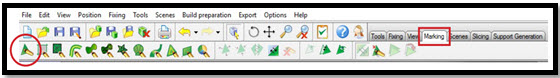
2. To start the Fix Wizard, go to Fixing > Fix Wizard
3. Magics will ask about
if you want to change the memory state of
the part: say Yes.
4. The Fix Wizard should load with the Diagnostics page highlighted. If not, click Diagnostics from the left menu.
5. To
run Diagnostics on your
file, click Update.


A green check (V) means
there are no
issues of that kind. Red cross (X) denote
specific
issues
with your file. Your mesh must have green check
marks in all fields
except Triangles
and Overlaps when
you submit your file for 3D printing.
Triangles and Overlaps must
be less than 300 each.
If your file has all green check marks and
less than 300 Overlaps or Triangles, we
are ready to Submit.


Common .STL file Error types explained.
1. Inverted Normals: In the STL
format, a normal indicates the outside of a triangle. When the normal points to
the wrong direction (the
inside), the triangle needs to be
inverted to have a watertight STL. This triangle is then called
a flipped triangle.

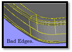
2. Bad edges: To have a
correct STL file, all edges of each triangle should be connected properly to a neighbor. If an edge is
not connected properly, the edge is called a bad edge and is indicated with a yellow line.

3. Bad contours: A group of bad
edges connected to each other form a bad contour.
a. Near bad edges: Near bad edges
are bad edges that are near other bad edges. These are mainly caused by 2 surfaces that are not
well connected.
b. Planar hole: A hole consists
of missing triangles. Use fill hole to fill it up.


4. Intersecting triangles: Intersecting triangles are triangles
cutting each other. It can happen sometimes that the STL surface has intersections.


5. Overlapping Triangles: An STL-file
sometimes has overlapping triangles. These triangles can be removed with the tools in the double
surfaces page. 2 triangles are considered as overlapping as:
a. The distance between them is smaller than the
given tolerance. (E.g. 0,1 mm
or 0,005 inch).
b. The angle between the normal of the triangles
is smaller than the given angle.
(E.g. 5°).


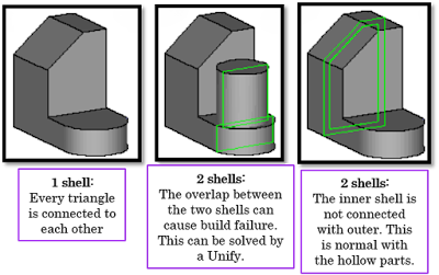
6. Shells: A shell is a collection of triangles
connected to each other. Normally a part has only one shell because every triangle of the part is
(indirectly) connected to every other triangle.

:
7. Noise shells: Some shells
have no geometrical meaning and are considered as noise (waste) that we can throw away. However,
it is recommended to look at these shells first before removing them.

 .
.

a. Conditional: Magics will only fill a contour when he recognizes it as a hole. Some contours aren’t holes.


Manual Fixing:


STL file fixing in detail.
Diagnostics (Advised way of working):
1. Use the check boxes to indicate what to analyze.
2. The result of the analysis is shown in bold,
the V or X indicates
if it's ok or not.
3. The features you can analyze. Click on the
link for an explanation of what they are.
4. To analyze the checked items.
5. This is the advise, based on the analyzed data.
6. This button will automatically apply the
advised fixing operation.
.

Tips and tricks:
Change the advice
You can influence the advice with the check boxes. When unselecting
a checkbox, the advice will not
take this parameter in account. When Magics keeps on sending you to a certain
fixing step, you can
skip it this way.
A full analysis is giving you the best result but
consider that:
a. Each analysis takes
time (especially the overlapping triangles and intersecting triangles)
b. In the beginning you often do not need all information (especially the overlapping triangles and
intersecting triangles).
c. Depending for what you're going to use your
STL-file afterwards, you may not need to repair
intersecting and
overlapping triangles.
Combined Fixing
(Advised way of working):
Automatic Fixing:
1. Press 

2. Magics will do a set of predefined actions.
3. Go back to the Diagnostics page to see the
results, by clicking on
 .
.
Manual Fixing:
Here you can decide yourself what
actions you want in the combined fixing.
Fix Normals: Magics will
reorient the normal of the triangles automatically. An
STL may not contain any inverted (red) triangles to be
watertight (= printable).
Stitching: Two bad edges (yellow lines) which are close enough to each other
can stitched automatically by pulling the open edges towards
each other. This
way, you get a watertight STL.
Tolerance: Here you indicate what distance a point may be moved to fix the near
bad edge.
Iterations: To get better results, the stitching is done in iterations, starting
with a small tolerance
and ending with the given tolerance.
Fill holes:
a. Conditional: Magics will only fill a contour when he recognizes it as a hole. Some contours aren’t holes.
b. Type of hole filling:
Ø Planar: The hole will be filled as it is a
planar hole.
Ø Freeform: Complex shaped contours are better
filled as free-form holes.
Ø Grid: The triangle size of the surface
that is used to fill the contour.
Unify: This will remove all internal geometry and intersecting triangles. This
operation will only be
done if the geometry allows it.
Filter sharp triangles: Sharp triangles will be removed to
improve surface quality.
Click on the Fix button in order to
execute the defined manual fixing.
Normal Fixing (Advised
way of working):
Automatic Fixing:
1. Press 

2. Magics will do an automatic orientation of the normal.
3. Check if all triangles are oriented correctly.
4. The default color of the inside of a triangle
is red. If you still see red triangles, they can be triangles with inverted normal (or a hole).
5. If there are still triangles with inverted
normal, orient them correctly with the manual tools.

Manual Fixing:

Stitching (Advised
way of working):
Automatic Fixing:
Automatic Fixing:
1. Press 

2. Magics will estimate a stitching tolerance.
3. Magics will stitch iteratively using this tolerance.
4. Check if there are still near bad edges.
5. Do a manual stitching with a higher
tolerance if needed.


Manual Fixing:
a. Tolerance: Magics will
reposition points to make triangles of different
surfaces fit correctly.
b. Iterations: To avoid errors caused by high tolerances, Magics can stitch in iterations, starting
with a stitch with a very small tolerance
and ending with the given tolerance.
Noise Shells Fixing (Advised
way of working):
Some
shells have no geometrical meaning and are considered as noise (waste) that we can throw away.
However, it is recommended to look at
these shells first before removing them.
Even
a shell of a few triangles can be
important.
Automatic Fixing:
1. Press  for automatic removal of detected noise
shells.
for automatic removal of detected noise
shells.
 for automatic removal of detected noise
shells.
for automatic removal of detected noise
shells.
2. If you're not sure you can remove
the noise shells manually.
3. The shells shown in a list sorted by amount
of triangles.
4. Use  to select
the noise shells.
to select
the noise shells.
 to select
the noise shells.
to select
the noise shells.
5. Press  to hide the
non-noise shells.
to hide the
non-noise shells.
 to hide the
non-noise shells.
to hide the
non-noise shells.
6. If the visible shells do not
represent important geometry, you can remove them.
7. Use  to delete them forever.
 to delete them forever.
8. If you're not 100% sure, you can
let the selected shells be a different part with the button  .
.
 .
.
9. It can be that there are other noise shells
present.

Manual Fixing:

Holes Fixing (Advised
way of working):
How to recognize a hole?


Automatic Fixing:
1. Press  for an automatic filling of the planar
holes.
for an automatic filling of the planar
holes.
 for an automatic filling of the planar
holes.
for an automatic filling of the planar
holes.
2. Magics will fill all the planar holes.
a. Non planar holes will not be filled.
b. Planar holes will not be filled if the
"new" triangles would intersect existing triangles.
3. Check the part.
4. The new triangles (used to fill the holes)
are marked.
5. Check if there are still holes left (non
planar holes will not be filled automatically).
6. Use the manual tools to fill the holes that
are still left.
7. Use Ruled and Free-form as fill-type for the
non-planar holes.


Manual Fixing:
First
you’ll need to identify what kind of hole you're dealing with:


Triangles Fixing (Advised
way of working):
Automatic Fixing:
1. Press  for an automatic fixing of triangles.
 for an automatic fixing of triangles.
2. Magics will run some algorithms that will remove untrimmed surfaces and intersections.
3. Because it will give bad results when a bad
edge is intersecting a triangle, the
automatic algorithm will be aborted.


Overlaps Fixing
(Advised way of working):
Automatic Fixing:
1. Press  for an automatic fixing of overlaps.
 for an automatic fixing of overlaps.
2. Your piece needs to have less than
300 Overlaps for submission in the 3D Printing Center.
3. If you cannot achieve this with
Automatic Fixing, you will need to manually fix the errors.


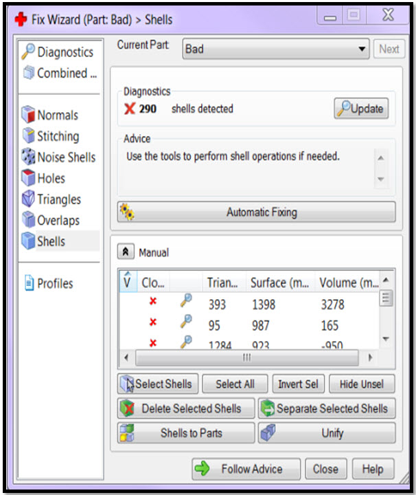
Shells Fixing (Advised
way of working):
It
can happen that your part consists of multiple shells. Use this tool to
manipulate the
shells. Because
this is not really an error, there's no
automatic way to solve this
problem.
Automatic Fixing:
Automatic Fixing:
a) Shell
list

b) Manual

If the Automatic
Fix does not get rid of extra
shells or combine
your shells into one, you can use the Manual Fix to do these operations. First, you must determine why there
are extra
shells. Go into the Shells tab in the Fix
Wizard, then extend the window down so
you can see more of the shells listed.
Click on a shell in the dialog
box, and Magics will highlight in green. Click on each individual shell
to see which piece of your object it is. You will be able to determine if the
individual shells are pieces you need to keep or if they can be deleted. If
they can be deleted, select the ones you would like to delete, and click Deleted
Selected Shells.
Tip
1: Hold
SHIFT and click to select multiple
shells for deletion.
Tip 2: Keep an eye on the triangle count of
your shells. Shells at the top of the list have many triangles, and these are likely to be the main
pieces of our object. Shells with very few triangles, at the bottom
of the
list, could be extra geometry that we don’t need.
After
deleting unnecessary
shells, click Update to see if the problem has been fixed. If not, use the Automatic Fix on the
Shells page, and Update again. Return to the
Diagnostics
page and Update to see the new status of your piece.


Future Prediction for Additive Manufacturing/ 3D-Printing (AM).

The Gartner Hype Curve on Additive Manufacturing/ 3D-Printing.


No comments:
Post a Comment