The
AM process begins with a 3D model of the object, usually created by Computer
Aided Design (CAD) software or a scan of the existing artifact. Specialized
software approximate this model with the help of raw, unstructured triangles (similar to the principle of meshing) and this approximation will
generate a new file format which is termed by the name as .STL (STereoLithography or Standard
Tessellation Language) file format.
Completely new file format i.e.
.STL file will be sent to the AM machine to begin the building process of the
prototype. Thus AM machine will creates defined object by adding layer upon layer ("Layer by Layer" principle) of
material on top of each other. This process will continue till a final 3D-component has been fabricated. For understanding the process workflow of Additive Manufacturing/3D-Printing do refer the image below which can let us understand the entire process chain which has to be follow for part fabrication.

Figure 1: Additive Manufacturing Process Chain.
Export .STL files in different CAD software’s.
Nowadays, there are several solid modelling packages are available in the market each having different layout for STL file generation from CAD data. Depending upon each software layout for STL file generation kindly refer to the below images.


Figure 2: STL file generation in different software packages.
Tessellation can be defined as a tiling of a plane using one or more geometric shapes but here these shapes are in the form of differently sized triangles. These triangles are used to approximate a 3D CAD model which can be further used for slicing purpose. Before slicing of an STL part will begin it should be make sure that the STL file is properly fixed and corrected.

Figure 3: CAD model to STL Conversion.
Fixing of an STL file can be done using softwares like Materialise Magics, ANSYS SpaceClaim, Autodesk Meshmixer, etc.
Even nowadays STL fixing can be done simply by using Internet, there are many online sources are available which can let us fix STL files. These online sources are: Materialise Cloud, MakePrintable, Sculpteo, Trinckle, 3D Tools, etc.

Figure 4: Representation of CAD versus Tessellated model.
Standard Tessellation Language (.STL) file.
The
STL file was created in 1987 by 3D Systems Inc. when they first developed the STereoLithography (founding father Chuck Hull). The
STL file,
as the de-facto standard, has been used in many, if not all, additive
manufacturing systems.
An
STL file consists of lists of triangular facets. Each
triangular facet is uniquely identified by a unit normal vector and three
vertices or corners. The unit
normal vector is a line that is perpendicular to the triangle and has a length
equal to 1.0. This unit length could be in mm or inches and is stored using 3 numbers. Since
each vertex also has 3 numbers, there are a total of 12 numbers to describe
each triangle.
The
STL file itself holds no dimensions so
the AM machine operator must know whether the dimensions are mm, inches, or
some other unit. The STL
file is normally labelled with a “.STL” extension that is case insensitive. These
files only show approximations of the surface or solid entities and so any information concerning the colour, material, build layers, or history is ignored during the conversion process.
STL files can be output as either Binary or ASCII (text) format.The ASCII
format is less common but easier to understand and is generally
used for illustration and teaching.
format is less common but easier to understand and is generally
used for illustration and teaching.

Figure 5: An original CAD model converted into an
STL file using different offset height (cusp) values, showing how the model
accuracy will change according to the triangle offset.
Understanding the .STL file resolution.
The STL file format uses a series of linked triangles to recreate the surface geometry of a solid model. When you increase the resolution, more triangles will be used, approximating the surfaces of the 3D model better, but also increasing the size of the STL file.
Number of triangles associated with the STL file will strongly effects parts resolution (as shown in figure 6). If we continuously increase number of triangles no doubt resolution will be much better but it will increase size of the file which will cause more time in slicing and also leads to hanging problem.

Figure 6: Resolution vs number of triangles for a ball.
Adaptive slicing can be used to for slicing a 3D model instead of Normal slicing which results in choosing higher layer thickness for simple or plane areas and lower layer thickness for curvy areas. This can be better understood from the following figure.
Number of triangles associated with the STL file will strongly effects parts resolution (as shown in figure 6). If we continuously increase number of triangles no doubt resolution will be much better but it will increase size of the file which will cause more time in slicing and also leads to hanging problem.

Figure 6: Resolution vs number of triangles for a ball.

Optimization of STL file.
There
is typically some control over the size of the triangles to be used in the
model. Since STL uses planar surfaces to approximate curved surfaces, then obviously the
larger the triangles, the looser that approximation becomes.
Most CAD systems do not directly limit the size of the triangles since it is also obvious that the smaller the triangle, the larger the resulting file for a given object. An effective approach would be to minimize the offset between the triangle and the surface that it is supposed to represent.
However, in practice the number of triangles cannot be increased
indefinitely. The resolution of STL files can be controlled during their
generation in a 3D CAD system through tessellation parameters. For example,
the STL generation process can be controlled by specifying the chord height or the angle control as shown in figure below.
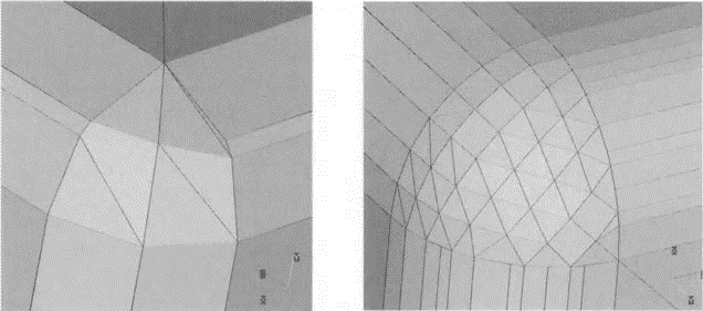
Figure 8: STL
files generated by applying Chord Heights of 0.5 mm (left) and 0.05 mm (right).
Chord Height.
The chord height is the maximum distance that your software will allow
between the surface of the original 3D model and the surface of the STL file. Using a smaller chord height will help represent more accurate the
curvature of a surface.
between the surface of the original 3D model and the surface of the STL file. Using a smaller chord height will help represent more accurate the
curvature of a surface.
The recommended value for the chord height is 1/20th of the 3D printing
layer thickness and never below 0.001 mm (1 micron). This will always
result in an STL file with ideal accuracy for most 3D printing applications.
layer thickness and never below 0.001 mm (1 micron). This will always
result in an STL file with ideal accuracy for most 3D printing applications.
Angle Control.
The angular tolerance limits the angle between the normals of adjacent triangles. The default setting is often 15 degrees. Some software also specify this tolerance as a value between 0 and 1. Unless a higher setting is necessary to achieve smoother surfaces, the default value of 15 degrees (or 0) is recommended.

For understanding the optimization process let us take an example of a sphere (modeled in
PTC CREO-2.0) to be converted into .STL file.

Sphere (red lines indicating tessellation).

Effect
of chord height and angle control for step size 4 units.

Effect of chord height and angle control for step size 2 units.
Observations from the tables.
1. As
the chord height and control angle increase number of triangles
decreases there by decrease in file size too in both binary and ASCII file
formats.
decreases there by decrease in file size too in both binary and ASCII file
formats.
2. From
the table we can see that for the same chord height and angle control
file size
of ASCII format is more than binary format.
3. As
the step size decreases from 4 units to 2 units we can see that steep
change in
number of triangles.
How to create a good STL file.
Every
triangle edge in the STL has exactly two neighbors (as shown in figure).

There
are
no geometric overlaps or intersections in the model (as shown in
figure). An STL may be properly manifold but may still have overlaps and/or
intersections due to triangles intersecting or overlapping with each other
geometrically.
figure). An STL may be properly manifold but may still have overlaps and/or
intersections due to triangles intersecting or overlapping with each other
geometrically.

The
triangles should be defined clockwise, with the normal indicating the
"out" direction (as shown in figure).
"out" direction (as shown in figure).

The
triangles should share common corner node positions (the "vertex to
vertex" rule). There should be no gaps or free edges in the mesh of
triangles (as shown in figure).
vertex" rule). There should be no gaps or free edges in the mesh of
triangles (as shown in figure).

There
should be no intersections between the triangles' surfaces (as shown in
figure).
figure).

There
should be no triangle overlaps (as shown in figure).

If
your STL model has triangles with very high aspect ratio, the mesh will be
distorted, and the analysis results will be less accurate (as shown in figure).
distorted, and the analysis results will be less accurate (as shown in figure).
For a
mesh triangle, the aspect ratio is the ratio of the length of the longest
side (a) to the height perpendicular to that side (b). As a general rule, this
ratio should be less than 6:1.
side (a) to the height perpendicular to that side (b). As a general rule, this
ratio should be less than 6:1.
The program
can accept some triangles with very high aspect ratios (hundreds
or even thousands). However, try to keep the average aspect ratio below 6.
or even thousands). However, try to keep the average aspect ratio below 6.

Advantages of STL file.
1. It provides a simple method of representing 3D-CAD data.
2. Second, it is already a de-facto standard and has been used by most
CAD systems and additive manufacturing systems.
3. It can provide small and accurate files for data transfer for certain
shapes.
4. It is robust facet model.
Disadvantages of the STL file.
1. The STL file can be larger in size than the original CAD data file for
a given accuracy parameter.
2. The STL file carries much redundancy information such as
duplicate vertices and edges the geometry flaws exist in the STL file
because many commercial tessellation algorithms used by CAD vendor
today are not robust. This gives rise to the need for a “repair
software” which slows the production cycle time.
3. Finally, the subsequent slicing of large STL files can take many
hours.
However, some AM processes can slice while they are building the
previous layer and this will alleviate this disadvantage.
Alternatives to STL file.
1. Cubital
company has
developed an alternative format called the
Cubital Facet List (CFL).
It uses facets to describe the model, yet the files are several times smaller
than equivalent STL files. The
CFL format stores the facet descriptions
without storing redundant information.
2. An STL
file unnecessarily repeats information, such as sets of coordinates
and strings
of text.
STEP,
the Standard for The Exchange of Product model data is a
proposed International Standards
Organization (ISO) standard for
electronic data exchange.
electronic data exchange.
3. IGES,
Initial Graphics Exchange Specification is an international
standard used by most CAD vendors. The
format is supported to allow file
interchange between different vendors, the
size
of an IGES file is typically
very large and difficult to handle.
4. SLI (SLIce),
Slice
format is the format used by the stereolithogrphy
machines to control the laser beam. It is
a series of vector commands
generated by the slicing software. The format
is proprietary, as are many
machine specific formats.
5. SLC (StereoLithography Counter) is 3D
system's proprietary control
data, layered based format. It is in fact a
2 1/2 dimensional contour
representation of a CAD data model. It can be generated from Solid or
surface modelling
software.
6. 3D Manufacturing Format (3MF) is a file format developed and
published by the 3MF Consortium.
3MF is an XML-based data format designed for
using additive manufacturing including information about materials,
colors, and other information that cannot be represented in the
STL format.
using additive manufacturing including information about materials,
colors, and other information that cannot be represented in the
STL format.
7. Additive Manufacturing File Format (AMF) is an open standard for
describing objects for additive manufacturing processes such as 3D printing.
The official ISO/ASTM 52915:2013 standard is an XML-based format
designed to allow any computer-aided design software to describe the shape
and composition of any 3D object to be fabricated on any 3D printer. Unlike
its predecessor STL format, AMF has native support for color, materials,
lattices, and constellations.


Siemens Additive Manufacturing Forecast Trend for next five
years.
years.


