Additive Manufacturing (AM) prints mechanical parts with an extreme degree of complexity, giving form to supposedly impossible geometries and about every imaginable shape that anyone can think off.
With AM, engineers can emphasize on design or functional optimization, rather than machinability associated with the component. However, such potential for design refinements strengthens the need for ensuring that metal AM leads (at least) to similar mechanical properties than Traditional Manufacturing processes (Casting, Forging, Milling, etc.).
With AM, engineers can emphasize on design or functional optimization, rather than machinability associated with the component. However, such potential for design refinements strengthens the need for ensuring that metal AM leads (at least) to similar mechanical properties than Traditional Manufacturing processes (Casting, Forging, Milling, etc.).

Micro-structural characteristics of the part completely defines the Mechanical properties associated with the component. Powder suppliers majorly focus upon certain important mechanical properties which will determine the component behavior under stringent operating conditions. They basically focuses upon:
Hardness
Ultimate tensile strength (Rm)
Yield strength (Rp 0.2%)
Elongation at break (A%)
Young’s modulus (E)
Fatigue (σd)

Additive Manufacturing (AM) metallurgy has its own unique set of processing-structure-property
relationships, although many aspects involve powder and welding metallurgy. Processing can
impact material micro-structure (size, shape and orientation of grains or crystals), which will alter the mechanical properties of the metal alloy.
relationships, although many aspects involve powder and welding metallurgy. Processing can
impact material micro-structure (size, shape and orientation of grains or crystals), which will alter the mechanical properties of the metal alloy.
For example, certain alloying additions can make an alloy too brittle for rolling, forging or other wrought processing. Casting, powder metal and additive processes might be the only way to produce certain highly alloyed materials. The chemistry or composition of the alloy can also change.
For instance, Titanium alloys will pick up oxygen, which will strengthen titanium up to a point. But if oxygen levels become too high, the titanium alloy will be brittle and crack. Powdered metals are also susceptible to contamination by oxygen and nitrogen, depending on the metal alloy. NASA researchers found increased nitrogen levels in nickel super-alloys resulted in increased grain sizes in AM parts.
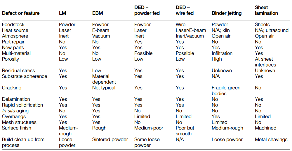
Comparison of process features, capabilities and defects across primary metal additive and 3D printing processes.
Density and Porosity Levels.
Even though powder-bed based AM may be the unique process able to print controlled porosity parts (filter elements, fluid permeable components), most developments (process and powders) have been focused on getting denser materials to maximize material properties and minimize defects generation (including micro-porosity and lack of fusion between neighboring layers).
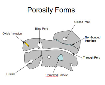
Forms of pores, cracks, inclusions, unfused particles and other defects in deposited materials.
In order to produce parts with higher density in combination with low surface roughness, one needs to
optimize the most influencing parameters for a specific material, which can be divided into four groups:
optimize the most influencing parameters for a specific material, which can be divided into four groups:
1. Material specific parameters (grain shape, size, distribution, flowability, etc.)

2. Laser parameters (laser beam power, spot size, focal point, etc.)

3. Scan parameters (scan velocity, hatch distance, etc.)

4. Environmental parameters (protective gas atmosphere, ambient temperature, O2 level)
Generally, the densities reachable with AM are similar or better than those attained with metal injection
molding or casting. AM parts can reveal a density higher than 99.5% and defects usually smaller than 50 µm (<100 µm for IN718). While a residual porosity can’t be avoided in AM powder bed based processes, it can still be minimized.
molding or casting. AM parts can reveal a density higher than 99.5% and defects usually smaller than 50 µm (<100 µm for IN718). While a residual porosity can’t be avoided in AM powder bed based processes, it can still be minimized.

It is noteworthy that material’s heterogeneity, thus porosity, has a very detrimental influence on fatigue
resistance because of a higher likelihood of crack initiation at pores close to the part surface and
subsequent propagation. More moderately, others mechanical properties (yield strength, corrosion
resistance, ductility) are also sensible to density.
resistance because of a higher likelihood of crack initiation at pores close to the part surface and
subsequent propagation. More moderately, others mechanical properties (yield strength, corrosion
resistance, ductility) are also sensible to density.
Powder quality has a significant impact on the ability to produce components that meet stringent
specifications consistently. The powder layer density should be as high as possible in order to produce
dense parts with high scan velocities and therefore with high productivity. The density of a powder layer is particularly dependent on the particle shapes, sizes or more exactly size distributions.
Particle shape influences porosity because a greater deviation from spherical shape leads to a lower
density, thus more porosity. Additionally, spherical shape also offers better flow properties during recoating.
density, thus more porosity. Additionally, spherical shape also offers better flow properties during recoating.
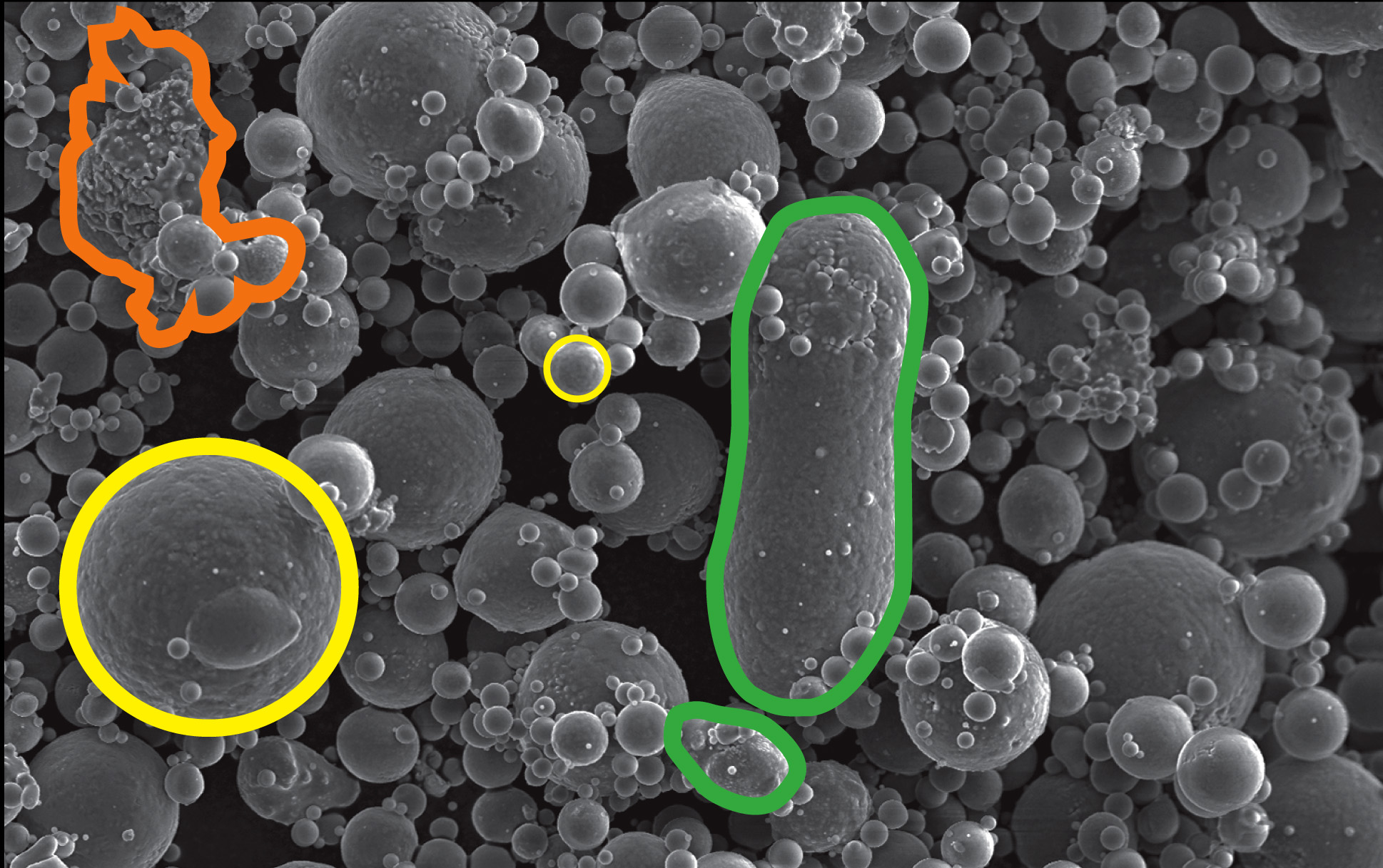
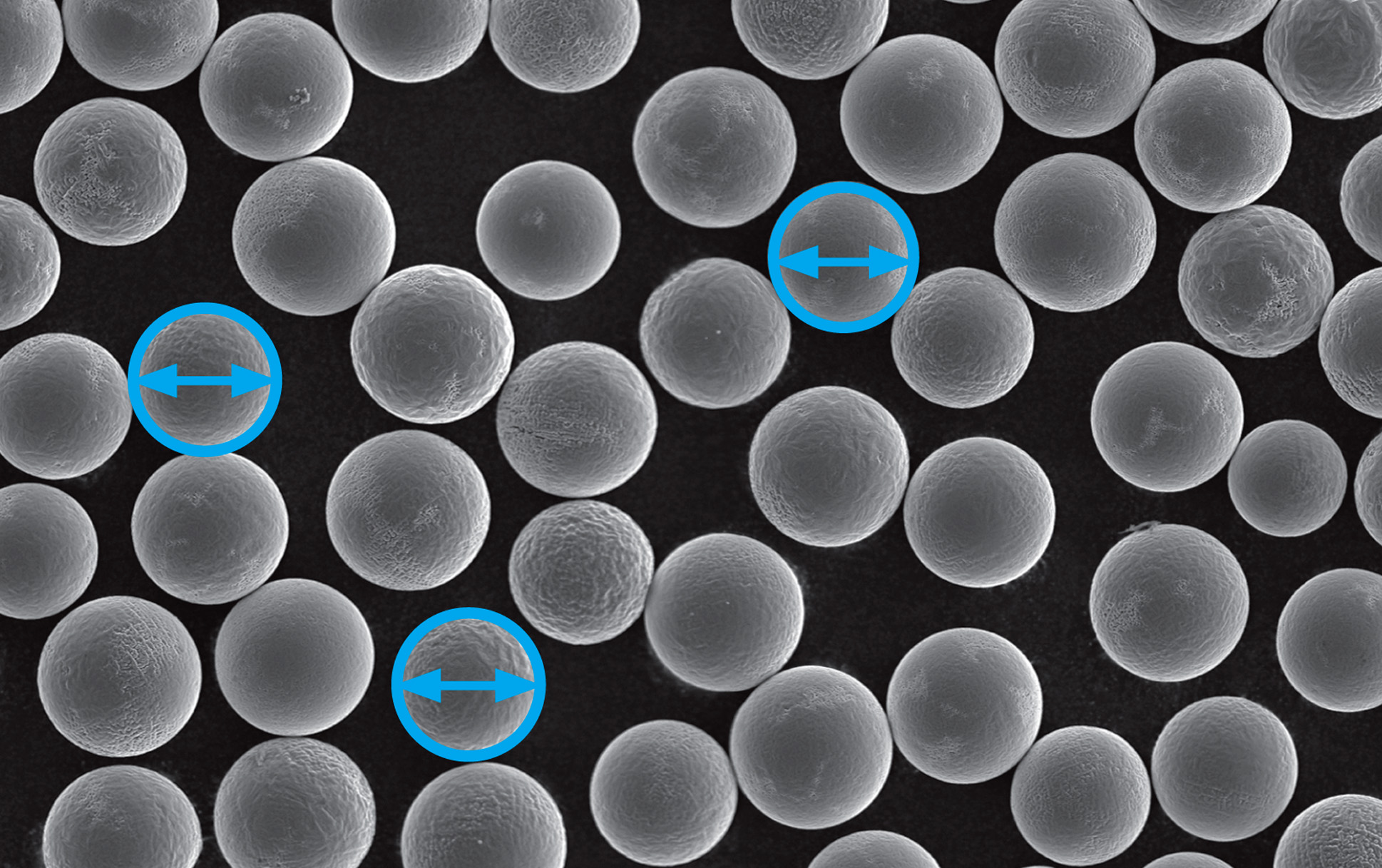
SEM micrograph of spherical and agglomerate free powder.
Particle size defines how easily it melts and the final pore size. While a fine powder granulation generally leads to better densities and surface qualities than a coarser material, a particle size distribution has to be qualified against the background of the layer thickness selected.

Surface finish and Fatigue Life.
Each material has a specific weakening behavior when exposed to repeatedly applied loads, which is called fatigue. In the case of Fe or Ti based alloys, it is possible to determine the fatigue limit below which fatigue failure should never occur.

AM surfaces tend to be rougher compared to conventional processes. Rougher surface finishes reduce fatigue strength compared to polished samples. Additive parts can be machined, ground, honed or polished to enhance the surface roughness, measured as Ra, or other surface finish attributes.

Isotropic super finishing processes might allow surface finish improvements without alterations to the geometry of the additive manufactured-parts. Extrusion honing or abrasive flow machining could be used to refine the surfaces of internal channels or hollows.

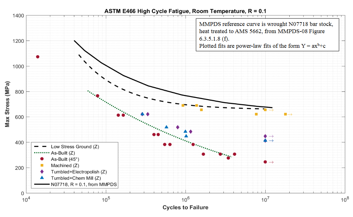
In the NASA technical report “Additive Manufacturing Overview: Propulsion Applications, Design for and Lessons Learned” by Kristin Morgan, engineering project manager from the NASA Marshall Space Flight Center, the fatigue performance of Selective Laser Melted (SLM) 718 nickel-based alloy (UNS N07718) was determined after various post-build surface finish enhancement treatments. Low-stress ground samples were the closest to approach the properties of the MMPDS design values for NO7718, as shown in figure above.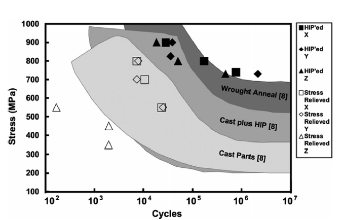
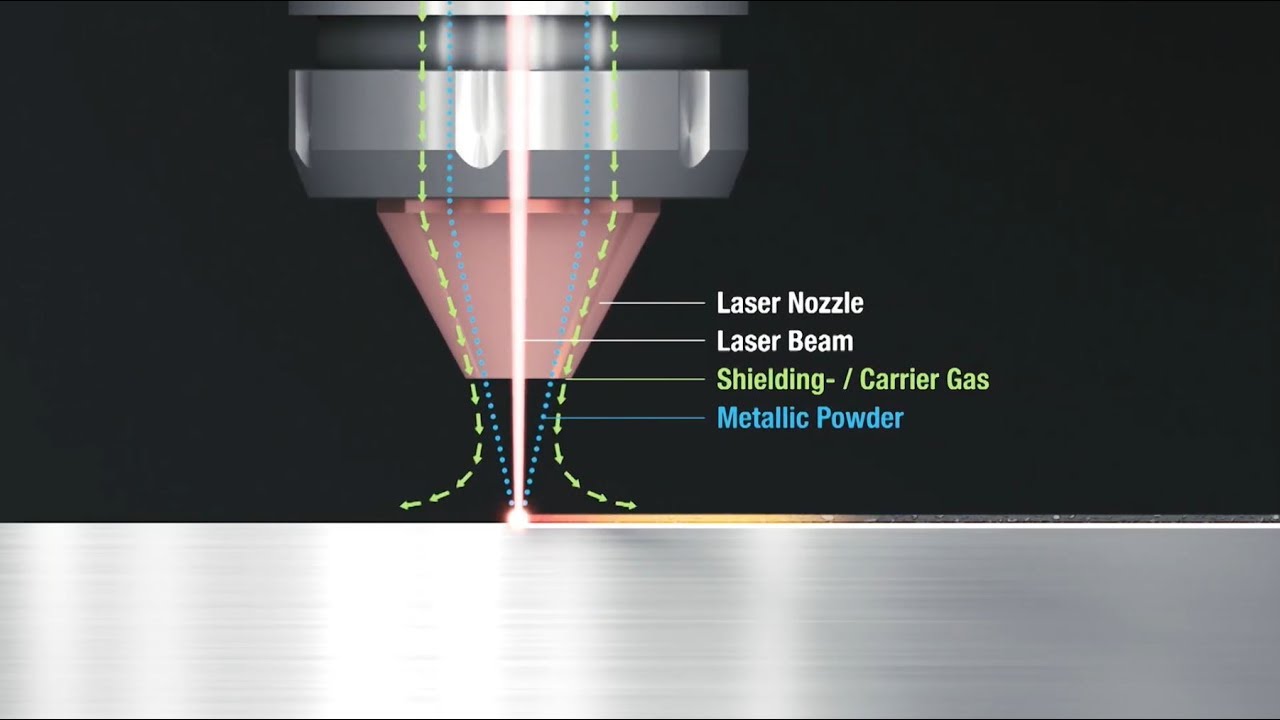
Fatigue test results comparing DED (Directed Energy Deposition), cast and wrought Ti6Al-4V titanium.
Shot-peening is a surface treatment where small balls impact on the part to induce compressive residual stress at the surface and slightly below. The sub-surface compressive residual stress field delays crack initiation and thus, postpones crack propagation.
Shot-peening method should be optimized to improve depth of compressive residual stress field while minimizing surface roughness.

Residual Stresses and Cracking.
When a part is additively manufactured, each layer or volume of material presents a complex thermal
history. It may involve several cycles of re-melting, re-solidification as well as multiple solid-state phase transformations. Combined with the high heat transfer rates attributable to "powder-bed" AM processes, post-built parts naturally contain high residual stresses that can distort geometry.


history. It may involve several cycles of re-melting, re-solidification as well as multiple solid-state phase transformations. Combined with the high heat transfer rates attributable to "powder-bed" AM processes, post-built parts naturally contain high residual stresses that can distort geometry.


From a preventive perspective, the level of residual stresses is dependant upon the material and build parameters. Moreover, to improve dimensional stability, a stress-relief annealing can be performed before removing parts from their platform (300°C during 2 hours to AlSi10Mg, for example).

High residual tensile stresses can cause cracks in components. Segregation, liquation and
shrinkage can occur during AM with melting and solidification steps. Liquation occurs because the lower melting constituents in an alloy solidify first, separating out during solidification. Upon
reheating, these liquated regions can cause liquation cracks, usually in the Partially Melted Zone
(PMZ) outside the weld pool.
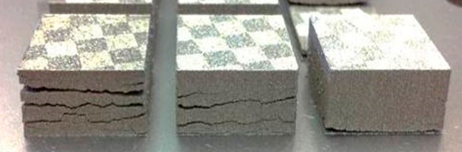
Layer delamination and cracking is a common a problem in selective laser melting (SLM).

Curling and pulling of edges from the supports due to residual stresses.

Catastrophic cracking of the component, or distortion of the build plate

Different scanning strategies for minimization of residual stresses.
Residual stress design tips:
•Avoid large areas of uninterrupted melt,
•Be careful about the changes in cross-sections,
•Select an appropriate scan strategy,
•Use thicker build plates where stress is likely to be high.
Heat Build-Up and Oxidation.
As successive layers are deposited, heat can build-up within an additive part that could lead to
grain or microstructure coarsening. The EBM process can take 5 to 80 hours to cool below 100°C after layer melting is completed, depending on part size and geometry, so an additive
manufactured-part may experience a significant amount of annealing and recrystallization within the AM process chamber.
Heating certain metal powders or parts in an air atmosphere can result in oxidation or oxide scale
formation, so the melting processes (LM, EBM, DED) use inert or vacuum atmospheres. If the atmosphere is not controlled within the metal deposition chamber, then oxidation and
contamination of the deposited metal can occur, which can embrittle alloys like titanium.
formation, so the melting processes (LM, EBM, DED) use inert or vacuum atmospheres. If the atmosphere is not controlled within the metal deposition chamber, then oxidation and
contamination of the deposited metal can occur, which can embrittle alloys like titanium.

High grade titanium will oxidize in an even gradient from blue to silver
Oxidation can also result in brittle oxide inclusions, which introduces a surface where cracks can
initiate. Aircraft grade alloys are often Vacuumed Arc Remelted (VAR) to produce a cleaner, more uniform alloy product with the superior properties required for critical service applications.
initiate. Aircraft grade alloys are often Vacuumed Arc Remelted (VAR) to produce a cleaner, more uniform alloy product with the superior properties required for critical service applications.

High-Temperature Oxidation of Fe3Al Intermetallic Alloy Prepared by Additive Manufacturing Technology LENS
Microstructural Control and Post-Build Processing.
Additive material properties have the potential to match or be enhanced beyond conventional
wrought and cast properties as the structural control of AM evolves. The AM process has been shown to break up reinforcing carbide or oxide agglomerates, which should enhance material properties.
wrought and cast properties as the structural control of AM evolves. The AM process has been shown to break up reinforcing carbide or oxide agglomerates, which should enhance material properties.
On the other hand, AM process build and post-processing parameters need to be closely
controlled to eliminate defects such as porosity (gas or process-induced), particle contamination from previous material runs (e.g., Nb particles in Ti6Al4V), unmelted feedstock particle inclusions, lack of fusion defects, cracks, high surface roughness, residual stress, warping and undesirable texture.
controlled to eliminate defects such as porosity (gas or process-induced), particle contamination from previous material runs (e.g., Nb particles in Ti6Al4V), unmelted feedstock particle inclusions, lack of fusion defects, cracks, high surface roughness, residual stress, warping and undesirable texture.
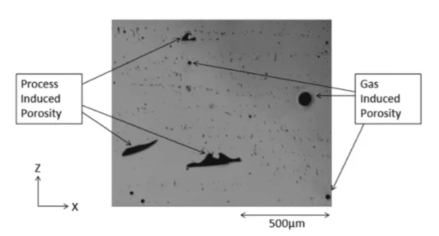
Gas and Process induced porosity levels observed using light optical microscopy.

Even slight powder contamination can ruin metal 3D printed component.

CT scan of a SLM printed specimen showing pores due to unmelting.
Proper post-build thermal processing, such as Hot Isostatic Pressing (HIP) and heat treatments, are often required to consistently attain equivalent or superior properties compared to the MMPDS database of statistically-based design values. Castings and jet engine blades are frequently HIP processed to close internal pores and provide fully-dense parts with improved fatigue, creep and toughness properties.

Hot Isostatic Pressing (HIP) schematic.
To ensure the quality of the production and maintain precise specifications, one has to manufactures
specimens to conduct an assortment of materials testing operations such as:
1 .Metallurgical / microstructure analysis
2. Chemical analysis
3. Mechanical testing
The following picture present a set of testing samples for metallurgical or microstructure characterization:

Metallurgical properties are analyzed on various sample sections in the XY plane and Z plane (Left).
Picture of an Inconel 718 super-alloy microstructure, micro-porosity of 0.02% maximum (Right).
Recent development in metal AM has resulted in reduced porosity and unique microstructures
with enhancing material properties. Future metal additive part integrity will be enhanced through
additional work on the development of improved machine reliability, NDE methods for quality assurance, process quality control and process control of feedstock raw materials.
with enhancing material properties. Future metal additive part integrity will be enhanced through
additional work on the development of improved machine reliability, NDE methods for quality assurance, process quality control and process control of feedstock raw materials.

Controlling process-structure-property relationships in metal additive manufacturing.
Additive Manufacturing Future Prediction.

Process Flow Criteria for Additive Manufacturing in Near Future.

Additive Manufacturing Future Prediction.

Process Flow Criteria for Additive Manufacturing in Near Future.