Introduction.
Cooling of the core insert is the greatest problem in most moulding
applications. With no core cooling, heating of the core is therefore
unavoidable. Current fabrication methods place severe limitations on the
configuration of the cooling channels used for heat withdrawal. Using Metal
Additive Manufacturing (M-AM) processes, Conformal Cooling Inserts can be
fabricated with ease. As a result, your cycle times are shorten while you
produce parts with lower residual stresses. This article will shed some lights
upon the design and manufacturing of Conformal Cooling Channel (CCC's) using
M-AM.
Basics of Injection Moulding Process.
Injection Moulding is the process of forcing melted plastic in to a
mould cavity. Once the plastic has cooled, the part can be ejected. Injection
moulding is often used in mass-production and prototyping and is a relatively
new way to manufacture parts, the first machines appearing in the 1930’s.
There are six major steps in the injection moulding process namely:
1. Clamping:
An injection moulding machine consists of three basic parts: the
mould, plus the clamping and injection units. The clamping unit holds the two
halves of the injection mould together during the injection and cooling.
2. Injection:
During the injection phase plastic material, usually in the form of
pellets, is loaded into a hopper on top of the injection unit. The pellets feed
into a cylinder where they are heated until they reach molten form. Within the
heating cylinder there is a motorized screw or ram that mixes the molten
pellets and forces them to end of the cylinder. Once enough material has
accumulated in front of the screw, the injection process begins. The molten
plastic is inserted into the mould through a sprue (channel), while the
pressure and speed are controlled by the screw.
3. Dwelling:
The dwelling phase consists of a pause in the injection process.
Once the molten plastic has been injected into the mould, the pressure is
applied to make sure all of the mould cavities are filled.
4. Cooling:
The plastic is allowed to cool to its solid form within the mould.
5. Mould Opening:
The clamping unit is opened, which separates the two halves of the
mould.
6. Ejection:
An ejecting rod and plate eject the finished piece from the mould.
The unused sprues and runners can be recycled for use again in future moulds.

Fig. 1. Injection Moulding Machine Operation.
Conformal Cooling.
In-mould part cooling is the most time-consuming part of the plastic
injection moulding process - reduce the time for part cooling and you will
increase production speed whilst achieving higher quality moulded parts with
less scrap. A variety of techniques have been used to maintain even
temperatures over the years, using methods such as bubblers, heat pipes and
complex drilling operations using laminated blocks. These, however, are
cumbersome, time consuming and can limit the useful life of a mould. Drilled
cooling channels are also limited to straight lines, no matter what the part
geometry.

Fig. 2. Conformal Cooling Design for improving quality of injection
moulded tennis ball.
Conformal cooling moulds have curved cooling channels that conform
closely to part geometry or contours and their use for an injection mould can
reduce cycle time by anywhere from 10% to 40%. The low range gains are possible
with little to no engineering analysis, the higher estimates reflect the use of
flow analysis, Computational Fluid Dynamics (CFD) and Finite Element Analysis
(FEA).

Fig. 3. Conformal Cooling Channel designs do require designing and
simulation expertise.
Whilst conformal cooling solutions can significantly reduce the
total cost of production by lowering mould cycle times, they also require
sophisticated mould designs. A well-designed conformal cooling mould typically
has a wide variety of unconventional curves, twists and shapes that must be
precisely placed. Once designed, these complicated moulds must be manufactured
to the same standards as any other mould.

Fig. 4. Sophisticated Conformal Cooling Channel Designs for
improving Process Efficiency.
By using non-traditional manufacturing method such as laser
sintering, cooling channel can be made in arbitrary geometry to fit the complex
product contour. This brings a better cooling efficiency and shorter cycle
time.
Direct Metal Laser Sintering (DMLS) is a very popular way these
days. EOS and Matsuura are two famous manufacturers of laser sintering
machines. Another method is Vacuum Brazing which can also be use for
manufacturing of conformal cooling inserts.
Injection Moulding problem solution using Conformal Cooling.
Traditional
Injection Moulding process faces a lot of issues such as: Sink Marks, Warpage, Cycle Time. Both Sink Marks and Warpage can reduce product quality which may
even cause part rejection from customer side.
Reasons for Sink Marks:
Non-uniform volume shrinkage due to thickness variation such as ribs
and boss are commonly seen on products for either functionality or strength
reinforcement purposes. These design can lead problems such as sink mark, void,
and stress concentration.

Fig. 5. Sink Marks visible on a Injection Moulded Component.
Possible Solution for Sink Marks:
Conformal cooling is one of the solutions for sink mark. Part
re-designing is suggested for minimization of sink marks which can be better
comprehend from the following figure:

Fig. 6. Sink Marks, Voids, Stress Concentrations in an Injection
Moulded Component.
Reasons for Warpage:
There are three major reasons for warpage i.e. Packing Pressure,
Temperature Distribution, Fiber Orientation. One of them is temperature
difference as shown in the picture.

Fig. 7. Non-uniform volume
shrinkage due to warpage.
Possible Solution for Sink Marks:
So, if the temperatures at core and cavity side and be more even,
warpage can be reduced. Conformal cooling can help in maintaining even
temperature differences along the component domain.
Reasons for Cycle Time:
Cycle time plays a vital role in Injection Moulding process because
it is one of the factor which will govern overall profit. Let us take an
example of a component which takes around 15 seconds for completion of process
cycle including Clamping, Injection, etc. We can say that time for one
component to get completed is 15 seconds i.e. Cycle Time is 15 seconds. Total around
5760 parts can be fabricated per day which leads to 2,102,400 parts in an year.

Fig. 8. Mould surface temperature comparison for conventional and
conformal cooling.
Now if by any means let us suppose by incorporating conformal
cooling in our existed design we are able to drop down the cycle time to 12
seconds (i.e. by 20%). Then our production values will change from 5760 parts
to 7200 parts in a day and 2,102,400 parts to 2,628,000 parts in an year. A
difference of ~520,000 parts which makes a lot of sense. So, by employing
conformal cooling we can achieve mould cooling at a faster rate which can
increase overall yearly profit.
Table 1. Evaluation of Net Profit a customer can earn by adoption of
Conformal Cooling.

Design Parameters
for Conformal Cooling.
Basically there are three important parameters for conformal cooling
design which are as follows:
1. Distance between pipes: a
2. Pipe diameter: b
3. Distance between pipe and cavity: c
Theoretically, c should be as smaller as possible. And the values of a and b are
dependent. However, mould strength and life cycle is a great concern. So, there
is a experimental design guideline for the three parameters as shown in the
figure below.

Fig. 9. Design guidelines for conformal cooling channel design.
With DMLS, the cross-section shape of the pipes can be changed, not
necessary to be circular. The feasibility criterion supposes a cross section,
which is self supporting. This means the angle of overhanging areas should be
above 40° to horizontal.

Fig. 10. Different cross-section geometries with justification of
fabrication.
The cooling performance can be increased due to the ribbed shape and
the higher expected turbulence in the channel (higher Reynolds number). Two
ejectors are bypassed in the space between without pushing the remaining wall
thickness to a critical limit.

Fig. 11. Design suggestion for an existed channel layout.
Manufacturing of Conformal Cooling
Channels.
1. Vacuum Brazing (VB):
Brazing is a metal-joining process where a filler metal is heated
and distributed between two or more close-fitting parts by capillary
action. Vacuum brazing is a precision brazing technique used to
join critical assemblies, many of which employ delicate or intricate features.
It employs vacuum as an ambient atmosphere so components undergoing the brazing
process will not react with excessive oxygen, moisture, nitrogen, or other
gaseous contaminants. By limiting the reactions with the surrounding
atmosphere, we can create a clean environment that is conducive to filler alloy
wetting and flow onto metal surfaces and into capillary joints.

Fig. 12. Basic Process layout for Vacuum Brazing Technique.
The filler metal is brought slightly above its melting (liquidus)
temperature while protected by a suitable atmosphere, usually a flux. It then
flows over the base metal (known as wetting) and is then cooled to join the
work-pieces together. It is similar to soldering, except the temperatures used
to melt the filler metal are above 450 °C (842 °F). The vacuum environment
can also reduce surface contamination from oxides and other compounds through
sublimation of the species due to chemical reduction. Maintenance of a clean
vacuum is essential to production of contaminant-free brazes.
Procedural steps of making
a mould insert using Vacuum Brazing technique:
1. Metal cutting:
Positioning of the multi-dimensional cooling channels into the
separating levels of the mould insert plates by means of CNC-controlled
treatment centres (milling, lathing, drilling).
2. Rough treatment of the
mould insert:
Pre-treatment of the contour before the mould insert is hardened by
2D-treatment (stages) or, if required, also 3D-treatment.
3. Cores with high thermal
conductivity:
In small mould ligaments, where a cooling channel is
technically/mechanically not possible, cores with high thermal conductivity are
inserted into the mould insert in a high vacuum procedure. Thermal conductivity
is increased by 15 to 20 times, compared to mould steel.
4. Joining technology:
By means of vacuum brazing, the individual mould levels are joined
together at their separating levels in a high vacuum procedure which protects
the joints.
5. Hardening:
Immediately after the joining procedure, the mould inserts are heat
treated depending on their steel specification, so that they acquire the
desired hardness.
6. Corrosion protection:
To protect the cooling channels from corrosion, special channel
coating is applied. It prevents the thermal conductivity of the cooling
channels from becoming impaired by corrosive media.
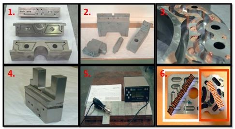
Fig. 13. Actual procedural steps for Vacuum Brazing of Conformal
Cooling Channels.
2. Matsuura Lumex-Avance25:
Matsuura, Japan are supplying machines under the trade name of
Lumex. It applies a hybrid technology which completes sintering and milling
stage in the same machine. Conformal cooling inserts can be easily fabricated
using this hybrid technology.

Fig. 14. Hybrid Laser Sintering machine supply by Matsuura
(Courtesy: Matsuura).
Firstly, there is a paving of thin layer metal powder (0.05 mm) then
laser sinter on this layer to cut the cross-section of the part. After
repeating this process ten times (0.5 mm), it uses blades to cut/mill the
product. Repeat the whole process till the part completes. At the end remove
the un-sintered metal powder to get the final part with the required design.


Fig. 15. Processing workflow in Lumex-Avance 25 (Courtesy:
Matsuura).
Video Link: Matsuura Lumex-Avance 25 in
process.
The LUMEX Avance-25 makes possible the creation of integrated
cooling pipes internally on any component, mould or die. Compared to
conventional post process cooling pipes, those created on the LUMEX are far
superior and efficient at cooling, contributing to a significant reduction in
injection moulding time.


Fig. 16. Matsuura Lumex can make Hollow Channels according to the
Contour Shape.
After part withdrawal from the machine it should be make sure that
there is no powder present inside the channels or at any other locations. If
powder remain present at unwanted locations this may cause powder sintering
during heat treatment stage and it will block the channels which we have
created.
Heat treatment is necessary to increase the hardness of the insert
so that it can withstand higher stresses during injection moulding process.

Fig. 17. Insert after age hardening can reach a hardness of 50 HRC
(Courtesy: Matsuura).
3. Electro Optical Systems (EOS) M290, M400-4 and M300-4:
EOS M systems produce final production parts by locally melting of
powder material with the help of high power lasers. In this way a 2D
cross-section of a part has been trace out by the laser and by stacking all of
these cross-sections together a 3D component can be created. This process is
termed as Direct Metal Laser Sintering (DMLS) which was introduced by EOS.
There are variety of powder materials available in the market from different
suppliers for particular usage. A proper combination of material powder and
process parameters can result in desirable mechanical properties.

Fig. 18. Direct Metal Laser Sintering (DMLS) processing workflow.
This technology gives us the benefit of making anything and remove
the barriers which were present for the designers. Process also has the
capability of making complex shapes which cannot be manufactured by traditional
means. That is the only reason people are adopting this technology for making Conformal
Cooling Channels in a much efficient way. Being a market leader in DMLS
technology EOS always try to improve the process capabilities so that we are
able to manufacture parts with more complexity and leverages the process in
different areas like Oil and Gas Industries, Automotive, Aerospace, Medical,
etc.

Fig. 19. EOS M DMLS systems M290, M400-4 and M300-4.
EOS supplies a variety of materials as per the demand from different
industrial sectors which are listed in the following image:
Table 2. Common material alloys for DMLS as per March 26, 2014 v13
(Courtesy: EOS).

Maraging Steel 1 (MS1, 18 Maraging 300 type steel (1.2709,
X3NiCoMoTi18-9-5)) supply by EOS has the desired mechanical properties which
can sustain higher temperatures and also have good strength compared to other
metal alloys available. For conformal cooling fabrication EOS MS1 is the best
option which can be easily processed up-to full density in any of the EOS M
systems.

Fig. 20. Insert with conformal cooling, built in EOS Maraging Steel
MS1 (Courtesy: EOS).
Table 3. Mechanical Properties achievable by EOS Maraging Steel 1.

* Data refer to parts built with
parameter set MS1_Performance 2.0.
** Hardness after age hardening can
shoot up-to 55 HRC.
Mould Temperature Difference in a Syringe Model.

Metal Additive Manufactured Tooling Embedding Conformal Cooling Channels.

"Education is the key. You need to educate your customers on what they can gain through AM - and also help them realize that if you want major improvements things just have to change."
-------to be continued.